
How to Make PCBs On a Desktop CNC Mill
This post provides an overview of how to design and prototype printed circuit boards (PCBs) on a desktop CNC mill. Most students do not have access to a CNC mill in their electrical engineering or electronics classes. In most classes, students make circuits using breadboards, which allows them to make connections by plugging wires and components into a grid. This method is great for very simple circuits, but it quickly becomes messy as circuits increase in complexity, to the point where it becomes very difficult to troubleshoot.
Prototyping circuit boards using a CNC mill has become a great way to create them quickly and accurately, and to see how components are connected. Designs can easily be tested and iterated upon to ensure that they work as expected.
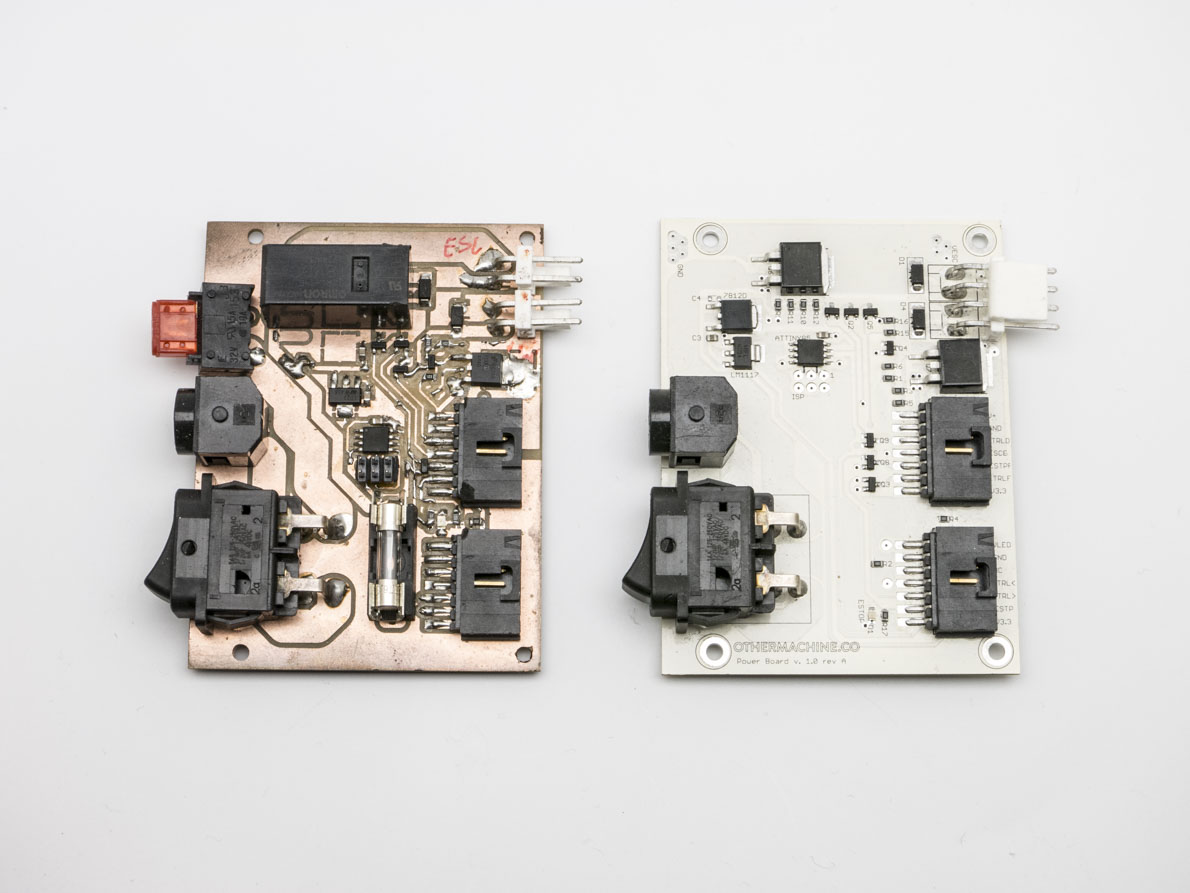
A milled prototype PCB next to the final production version. A few components were replaced or moved, but it’s more or less the same board.
Within the last few years, PCB manufacturers have adopted batching processes that allow people to order small quantities of production-quality boards at very low prices, with the caveat that it takes several days or weeks to receive your PCBs by mail. For the final, production-ready design, using a PCB manufacturer is great, but until you know that all the components are wired correctly in your design, that the board fits properly into your enclosure, and that it powers on and works as intended, it pays to be able to iterate quickly. This is where a desktop CNC mill can make a big difference. By creating an easy path from a digital PCB design to a physical, testable board, milling machines are the quickest way to get your designs ready for production.

For colleges and universities, where students are learning electronics or electrical engineering, applying those principles and quickly receiving feedback allows students to take their learning further. A desktop CNC mill allows students to iterate multiple times per class and test subsections of a board without needing to finish the entire design first. By the time students order a production-quality board, they’re confident that it’s going to work, and they have advanced their design further through the rapid iteration and testing they performed.

Milling a PCB on a CNC mill (200x speed).
The workflow of designing and milling a PCB has three parts.
Step 1: CAD
The first step of the workflow is CAD (computer-aided design), in which the designer uses software to create the circuit schematic and board layout. There are many software packages at many price levels for designing PCBs. We’re very fond of the free version of EAGLE, but there’s also KiCad (also free), Altium, DipTrace, Upverter, OrCAD, and many more.

Step 2: CAM
The second step in the workflow is CAM (computer-aided manufacturing), in which the designer uses software to generate instructions for the CNC machine based on the board layout. EAGLE has a plugin called pcb-gcode that will translate the board layout to G-code, which is the language of CNC machines. Most other PCB CAD software does not have such a plugin, so there’s an intermediate step of generating Gerber and Drill files. Gerber files are vector images that represent the board layout as coordinates and include other identifying information. Gerber is the standard format used within the PCB industry. Drill files, which usually use the Excellon format, are also commonly used. All PCB software should have instructions for how to generate Gerber and Drill files.

Once you have Gerber and Drill files, you can use CAM software such as FlatCAM, CopperCAM, UcamX, or CircuitCAM to create G-code files. Our Bantam Tools Desktop Milling Machine software will also turn Gerber files into G-code. We made a tutorial for FlatCAM because it’s free and very simple to use:

Step 3: Mill
The third step in the workflow is milling the board with a CNC machine using the instructions (G-code files) generated by the CAM software. This is where it can get a little confusing because there are many different CNC machines and CNC control software packages to choose from. For control software, Mach3 has a large following and runs on Windows. LinuxCNC is free, also has a large following, and runs on Linux. Both of these programs can run a variety of CNC machines.
There are many CNC machines to choose from, with a variety of pricing and feature options. Low-cost CNC mill kits are available, but these require hands-on assembly and maintenance, and they don’t have the same precision or ease-of-use as assembled machines. Ultra-high-end PCB mills are available with all sorts of bells and whistles — like vacuum tables, dust collectors, and through-hole plating — but they also have price tags that are often in the tens of thousands of dollars. We think the Bantam Tools Desktop PCB Milling Machine, our portable, fully assembled CNC mill, provides a great combination of precision and affordability. It also comes with really good software that’s easy for students and others who are new to milling to learn quickly.
Ordering Production-Quality Boards
Once your prototyping is done, you’re ready to start mass-manufacturing production-quality boards. You’ll want to order just one or two first to make sure they’re exactly right, but once they check out, it’s off to the races. Production-quality boards have features that milled boards don’t, such as a solder mask, plated through-holes, a silkscreen layer with text and graphics, and overall higher durability. They can be ordered from many different manufacturers, both domestic and international, with many different options for pricing and turnaround time. Here are some examples from PCBShopper for a 2"x3" two-layer board:

Each manufacturer should have instructions on how to submit Gerber files for manufacturing as well as minimum specifications. We at OMC have used OSH Park and Advanced Circuits and found them both to be great. Make sure to read reviews!
Hopefully this gives you a sense of the PCB design and milling workflow: CAD (and often Gerbers), CAM, milling, and then ordering boards from a manufacturer once the milled boards are proven viable. If I’d had this capability back when I was taking electronics, not only would I have spent less time building each circuit, but I would have been able to make my final project considerably more awesome. Learning some basic CAD would also have broadened my horizons and given me a lot more options when I made my own personal projects outside of class. Part of why I love working at Bantam Tools is that I get to help bring this technology to students and teachers everywhere.
As always, feel free to contact us with any questions. Happy milling!